Mother Nature is the mainstay of our lives, but in the race for development and self-interest, we have caused the greatest harm to this life-giving source. Nature is not an alternative, but the foundation of life. It is not merely forests, mountains, or rivers for us, but the purity of our breath, the greenness of the fields, the smiles of our children, and the greatest responsibility for our future.
There is still time to begin with one seed, one idea, and one change.
The main damages to the environment due to human activities are as follows:
- Deforestation: Forests are being cut down on a large scale for agriculture, urbanization and industries, thereby taking away the natural habitat of wildlife.
- Pollution: The air is polluted by smoke from factories and vehicles (air pollution) and the water sources are polluted by waste (water pollution).
- Climate Change: Due to excessive exploitation, the earth’s temperature is increasing, glaciers are melting and the weather cycle has become unbalanced.
- Indiscriminate use of natural resources: Excessive exploitation of groundwater and the race to extract minerals has disturbed the balance of nature.
Trees are our lifeblood, as they provide us with fresh air. Dense forests are called the lungs of our planet, as they purify the air. Trees are the very essence that gives us life. So why do we cut down these silent, charitable trees without even protesting? How long will we continue to cause our own destruction? Agricultural expansion, urbanization, and industrialization are causing severe forest degradation. Forest-natives are dying. Indiscriminate deforestation is destroying the habitats of wild animals, forcing them to frequent human settlements. Deforestation has increased pollution. Not only are forests gradually being wiped out, but trees in settlements are also disappearing, and we are losing the joy of standing in the shade of a tree. It is said that happiness resides in the forest. Indeed, forests are the protectors of the climate. Forests are the only shelter for wild animals.
Forests are rapidly disappearing worldwide. It is known that approximately 3.1 billion cubic meters of wood is harvested from forests annually for timber and fuel. Globally, 13 million hectares of forest are being completely destroyed each year, marking the complete end of forest civilization. The deterioration of forests is altering the climate and causing widespread changes in the climate. Because trees absorb carbon dioxide and store carbon, forests are carbon accumulators. Estimates indicate that 283 gigatons (109) of carbon are stored as biomass in all the world’s forests. In addition to living plants and trees, forests also contain carbon in the form of biological waste. Therefore, the carbon content is even higher than in the atmosphere. The loss of trees from forests is causing a loss of 101 gigatons of carbon annually, a cause for concern. Forests, and this concern, are losing precious resources. Forests are constantly shrinking, and we don’t even realize what precious things we’re losing. We must be serious about planting trees.
Trees are our best friends. Dense pine forests once existed in the mountainous regions, teak forests in the Terai region, sal forests in the plateaus, and shisham trees in abundance in the plains. It’s said that forests provide life. We must certainly accept this. Many trees have been described as special, including the peepal tree, which releases abundant amounts of oxygen. When the peepal’s golden leaves sway with a slight breeze, life-saving air flows. The peepal’s large canopy of foliage rapidly absorbs carbon dioxide. Its roots penetrate deep into the ground and provide water. In addition to the Peepal tree, trees like the Neem, Banyan, Mango, Pakhar, Gular, Jamun, Mahua, Tamarind, Dhak, Sal, Teak, Kachnar, Gulmohar, and Amaltas are all highly beneficial to the environment. Each tree is useful in many ways. It is certainly a permanent yogi. Different tree species have their own unique characteristics. Peepal, Neem, Pakhar, and the native Acacia tree prevent soil erosion and enhance soil fertility.
Tulsi, Ashwagandha, Haridra, and Aloe Vera have medicinal value. Tulsi is the reason why we know the significance of Vrindavan, which is always present in every home’s courtyard. Many trees play a vital role in controlling pollution. These include Neem, Amaltas, Sheesham, Banj (Oak), Peepal, Molshree, Mango, Jamun, Arjun, Sagwan, and Tamarind. Babul, Gulmohar, Arjun, Siras, Kadamba, and Amaltas trees make barren, moist, and garbage-filled land useful. Noise is also increasing as a form of pollution. Among the trees that control noise pollution, Ashoka, Neem, Banyan, Kachnar, Peepal, and Semal are the most important. Trees that absorb gaseous pollution include Bael, Bougainvillea, Sheesham, Peepal, Mahua, Tamarind, and Neem. Experts recommend planting lemongrass, palmrose, vetiver, chamomile, blackgrass, khus, citronella, and Java grass on barren, alkaline, saline, and heavily metal-polluted land. The point is that trees are embodiments of Shiva, absorbing the poison of our surroundings and granting us protection. It’s shameful that we don’t hesitate to axe even such Shiva-like trees.
We receive so much from trees, both articulated and unarticulated. Every flower on a tree shares love. Trees teach us moral lessons, including adherence to ethics and natural imitation. In our life filled with despair, hope, faith, and patience are absolutely essential. These lessons come naturally to us from trees. When a person sees that even a tree reduced to a stump or devoid of branches, after a few days, becomes lush and green again when the time is right, all their despair is allayed. Filled with renewed enthusiasm and courage, they move forward. It can be said that his hopes also blossom; this is green faith. This is what our scriptures say –
“Chhinnodpirohti taru: ksheeno-tyupachiyate punaschandra:.
Inti vimrishant: santak: santakpyante na te vipada.”
When we internalize the spirit of this verse, the impurity vanishes from our faces. A smile begins to dance on our lips. We love nature. Greenery and prosperity appear everywhere. The Horticulture Department is working to instill green faith. Now, with the efforts of experts, an effort has been initiated to rejuvenate old trees. This work will be carried out under an operation, half the cost of which will be borne by the government. A thirty-year-old tree will be made three years old.
This involves cutting off all old and diseased branches from the tree. The new shoots that grow from these parts will be treated and a healthy plant will be created. Within about two to three years, the tree will be laden with mangoes again. It’s known that as a mango tree ages, its yield weakens. According to experts, sometimes by the age of ten to twenty years, the tree becomes so weak that it doesn’t even bloom. Now, even these old, diseased trees will be able to grow orchards. This is commendable. Ironically, while meaningful efforts are being made to revive dying trees, lush trees are also being cut down. Trees break. When a tree breaks, I feel as if someone has torn off my arm. It is our responsibility to understand the pain of trees and not let them break, that is why I say that choose a tree and quickly plant it on some sad land so that there is lush greenery and happiness blossoms. Taking small steps at the individual level is crucial to improving the situation and protecting future generations. The Indian government and various environmental organizations are also running numerous awareness campaigns and policies to this effect.
Deforestation & Buildings
- Destruction of lush green forests: Tall buildings and societies are being constructed by cutting down trees.
- Wildlife habitats are disappearing: Due to the reduction in forests, wild animals are moving towards cities and villages.
- Increase in global warming: Due to reduction in trees, carbon dioxide is increasing and the temperature of the earth is continuously increasing.
Mining & Mountain Destruction
- Hollowing out the mountains: Blasting and mining is going on rampantly in the mountains for gravel, stone, coal and precious minerals.
- Danger of Landslides: Due to weakening of the foundation of the mountains, massive landslides are occurring in the mountains every year, causing huge loss of life and property.
- Changing course of rivers: Due to breaking of mountains, natural water sources and rivers are changing their course or drying up.
Its serious consequences
- Deterioration of weather: At some places there is severe drought, while at other places there is flood out of season.
- Air and water becoming poisonous: Due to lack of trees, pure air is disappearing and due to concrete, water is not able to go inside the ground.
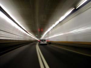
If we don’t act now, this “development for show” will spell doom for future generations. Progress is necessary, but not at the expense of nature. Humans have drastically altered the natural environment for their own progress and convenience. They have carved tunnels through mountains, built dams to block the natural flow of rivers, and established huge factories for production. We used to dig up roads to put trains underneath – cheaply. Ever-better tunnel boring machines have made the disruption this causes unnecessary. Tunneling is one of the many technologies that make modern civilization possible. For one, a tunnel can dramatically reduce transportation costs by shortening travel times between two points. The Holland Tunnel opened in 1927 as the first underwater vehicular crossing of the Hudson River between Manhattan and Jersey City, New Jersey. Once described as the “Eighth Wonder of the World,” at the time of completion it was the longest underwater vehicular tunnel, the first tunnel constructed with a ventilation system specifically designed to handle automobile and truck exhaust fumes, and had the largest tube width—twin tubes at 29.5 feet (9 m) in diameter, setting the standard for other vehicular tunnels throughout the world that followed.
Plans for the Hudson River crossing began in 1906 with the appointment of joint commissions in New York and New Jersey to construct one or more bridges between New York City and New Jersey.
In 1913, Davies estimated the cost of a tunnel at $10 million, compared to $50 million for a bridge in the same location. The commissions would later concur that a bridge was not economically feasible due to the long span that would be required to cross the Hudson River, the deep foundations that would be needed to reach bedrock, and the lengthy approaches would necessitate the purchase of large amounts of real estate.
Clifford Milburn Holland was appointed as chief engineer of the tunnel project and began work on June 15, 1919. Although he was just 36 years old, Holland was a well-known expert in underwater tunnel construction, having designed four subway tunnels across the East River including the IRT Clark Street Tunnel (2 and 3 trains), the BMT 14th Street Tunnel (L train), the BMT 60th Street Tunnel (N, R, and W trains), and the BMT Montague Street Tunnel (M and R trains). Educated at Harvard University, Holland received a Bachelor of Arts in 1905 and a Bachelor of Science in Civil Engineering in 1906. He enlisted the help of Ole Singstad to serve as the project’s design engineer and Milton M. Freeman to serve as the resident engineer and supervise construction.
 |
| The first tunnel with a ventilation system specifically designed for exhaust fumes from motor vehicles, the Holland Tunnel has four ventilation buildings. |
Eleven different plans for the tunnel were proposed, including a design by General George W. Goethals (who previously served as chief engineer of the Panama Canal) that included a single tube lined with concrete blocks having two levels, each containing three traffic lanes. Holland’s plan called for twin tubes lined with cast iron, each containing two lanes of traffic on a single deck, and was ultimately selected.
Meanwhile, experiments were conducted to provide the data necessary to design the special ventilation system for motor vehicle exhaust. Studies were made in Pittsburgh, Pennsylvania by the Bureau of Mines to determine the composition of motor vehicle exhaust gases, at Yale University to determine the effects of carbon monoxide on humans, and at the University of Illinois to determine the amount of power required to operate the ventilation system. It was concluded that the tunnel’s ventilation system would need to keep the carbon monoxide concentration below four parts per 10,000.
Previously, conventional ventilation systems in railroad tunnels were designed to blow air from one portal to the other. This type of longitudinal system would not work in a vehicular tunnel because it would require gale force winds of more than 70 miles per hour (113 km/h) to be blown through the tunnel to clear the exhaust fumes, which would also create a hazard if a fire broke out. Instead, a new type of ventilation system was devised in which clean air would be supplied throughout the tunnel through a fresh air duct located below the roadway with openings at regular intervals. An exhaust duct would be located above the roadway with openings at regular intervals to remove the diluted exhaust fumes out of the tunnel. Thus, air would be drawn straight up within the tunnel, which would confine the spread of flames in the event of a fire.
A 400-foot (122 m) long large-scale model of the tunnel was constructed by the Bureau of Mines near Pittsburgh, Pennsylvania to evaluate the effectiveness of the proposed ventilation system. Clifford Holland also traveled to Europe in 1921 to study the ventilation systems of tunnels in England, Germany, and Scotland. The Holland Tunnel has a total of 84 fans in four ventilation buildings that can completely change the air inside the tunnel every 90 seconds. Electric motors with an output of 6,000 horsepower are needed to drive all of the fans at once, although the tunnel normally operates with some of the ventilation fans shut off and held in reserve.
 |
| The Hudson River Vehicular Tunnel was named in memory of chief engineer Clifford Holland, who died two days before the tunnel was holed through. |
Construction of the project, then known as the Hudson River Vehicular Tunnel, officially began with a groundbreaking ceremony on March 31, 1922 at the foot of Canal Street in Manhattan. The tunnel was dug out from beneath the riverbed using six shields, each of which was a large cylinder driven by 30 hydraulic jacks with a total force of 6,000 tons (5,400 t). Compressed air was used to pressurize interior of shield to keep out the water and muck; after segments of the tunnel are excavated, 2.5 foot (76 cm) thick cast iron rings are added to support the walls.
Five years into the project, chief engineer Clifford Holland suffered a nervous breakdown as a result of the tremendous stress demanded by the work, having spent long hours working at this desk and in the compressed air of the tubes. He was sent to a sanitarium in Battle Creek, Michigan for rest but died of heart disease on October 27, 1924 at the age of 41. His death occurred just two days before the tunnel was to be holed through, and the celebration that had been planned was canceled in respect for the chief engineer. The two ends of the tubes from New York and New Jersey were joined together without fanfare, even though Holland’s mathematical calculations led them to meeting within a fraction of an inch (1 cm) of each other.
Clifford Holland had served as the director of ASCE from 1922 until his death and was one of the twenty members that attended the founding meeting of the ASCE New York Section on February 18, 1920. Following his death in October 1924, President John P. Perry wrote letters on behalf of the ASCE New York Section to both the New York State Bridge and Tunnel Commission and the New Jersey Interstate Bridge and Tunnel Commission asking that the vehicular tunnels under construction be named “The Holland Tunnels.” Today, the Holland Tunnel remains one of the few major engineering works that have been named after its engineer. The official proclamation issued by the commissions read as follows:
| The Holland TunnelAt Stated Meetings of the New York State Bridge and Tunnel Commission and the New Jersey Interstate Bridge and Tunnel Commission held Tuesday, November twelfth, nineteen hundred and twenty-four, the following resolution was adopted.Whereas the untimely death on October twenty seventh, nineteen hundred twenty four ofClifford Milburn Holland Chief Engineer in the Construction of the Hudson River Vehicular Tunnelhas caused a general expression of sorrow; andWhereas, by comment in the public press as by resolutions of public bodies and societies and expressions from leading citizens and civic organizations, the opinion is general that Mr. Holland gave his life to the work of the planning and construction of this great public utility; andWhereas, the members of the New York State Bridge and Tunnel Commission and the New Jersey Interstate Bridge and Tunnel Commission are in accord with the widespread suggestion that some fitting attribute be paid to the memory of the deceased Engineer; Therefore be itResolved, that the Hudson River Vehicular Tunnel, now being constructed between Canal and Broome Streets in the Borough of Manhattan, City of New York, and 12th and 14th Streets, Jersey City, New Jersey, be and it is hereby dedicated to the memory of Clifford Milburn Holland, and that the said Hudson River Vehicular Tunnel is hereby designated and named asThe Holland Tunnel |
Following Clifford Holland’s death, Milton H. Freeman took over as chief engineer of the Holland Tunnel but fell ill of acute pneumonia and died on March 24, 1925. He was succeeded by Ole Singstad, who oversaw construction of the Holland Tunnel for the next two and a half years until its completion. The Holland Tunnel formally opened on the afternoon of November 12, 1927 when President Calvin Coolidge used a golden telegraph key from his yacht in the Potomac River to part two large American flags draped over the entrances to the tunnel (the same key that was used to explode the final charge on the Panama Canal). Twenty thousand people walked through the tunnel during a two-hour period and viewed the engineering marvel before it was opened to vehicles at midnight. The first car to enter the Holland Tunnel from Manhattan carried chairmen of the New York State Bridge and Tunnel Commission and the widows of Clifford Holland and Milton Freeman. The New York entrance plaza was named Freeman Square in memory of the tunnel’s second chief engineer.
 |
| ASCE and ASME formally designated the Holland Tunnel as a National Historic Civil and Mechanical Engineering Monument on May 2, 1984. |
Stretching 8,557 feet (2,608 m) from portal to portal in the North Tube and 8,371 feet (2,551 m) in the South Tube, the Holland Tunnel cost $48.5 million to build and the expenses were equally shared by states of New York and New Jersey. A total of 5,250 feet (1,600 m) of the tunnel’s length is located underwater at a maximum depth of 93.5 feet (28 m) below the surface. The Holland Tunnel relieved traffic strains on ferries crossing the Hudson River, which previously required a transit time of 18 minutes and sometimes required motorists to wait on line for hours. It also facilitated the transport of goods across the Hudson River, which had previously served as a barrier to shipping materials between New Jersey and New York City.
The Port of New York Authority later acquired the Holland Tunnel in 1931 and assumed its operations. Although the opening of the New Jersey Turnpike diverted some of the traffic crossing the Hudson River to the Lincoln Tunnel and George Washington Bridge, the Holland Tunnel continues to remain a vital and heavily patronized crossing between Manhattan and New Jersey. Hugh L. Carey Tunnel
The twin-tube tunnel forms a key connection in New York City’s regional highway system. (photo courtesy of MTA Bridges & Tunnels)The Brooklyn–Battery Tunnel, renamed the Hugh L. Carey Tunnel in 2012, opened to fanfare in 1950. At the time of its opening, it was hailed for its planned cost and time savings in linking Brooklyn and Manhattan, offering connections to the region’s expanding arterial highway network. The tunnel also made headlines for being the longest continuous underwater, deepest, and most expensive vehicular tunnel in North America, and was the longest continuous underwater vehicular tunnel in the world. At 9,117 feet (2,779 m), it has held the designation as the longest continuous underwater vehicular tunnel in North America since its opening.
The twin-tube tunnel carries four total lanes of traffic and forms a key connection in New York City’s regional highway system that was constructed during the early-to-mid 20th century, including the Gowanus Parkway (now the Gowanus Expressway), Franklin D. Roosevelt Drive, and the West Side Highway (now Route 9A). The Gowanus Parkway was planned in conjunction with th Brooklyn–Battery Tunnel and granted the Brooklyn neighborhoods of Gowanus and Red Hook—both with heavy industry and shipping—easy vehicular access to Manhattan. Today the tunnel also serves as an important link in the public transportation system and is used by nearly 30 different express bus routes that operate between Manhattan and Staten Island or Brooklyn.
A crossing between the Battery in Manhattan and Hamilton Avenue in Brooklyn was first proposed as a tunnel in 1929. By the late 1930s, there were competing proposals for a crossing at the same location including a bridge proposed by the Triborough Bridge Authority (TBA) and a tunnel by the New York City Tunnel Authority (NYCTA). In 1939, the United States Department of War declined to issue a permit for a bridge, citing concerns related to the location of the Brooklyn Navy Yard upstream from the crossing, and New York City Mayor Fiorello LaGuardia publicly endorsed the construction of a tunnel.
TBA Chairman Robert Moses shows a model of proposed Battery Bridge. (photo from Library of Congress Prints and Photographs Division)On October 28, 1940, President Franklin D. Roosevelt presided over the groundbreaking ceremonies for the new tunnel. Although initial estimates for the project had a duration of four years, pauses for labor and materials shortages during World War II halted construction between 1942 and 1945, extending the timeframe to a decade. Efforts to prepare the tunnel for the pause in construction, which included the construction of concrete bulkheads and continuous pumping operations on the Brooklyn side, allowed work on the tunnel to resume only two months after the restrictions on labor and material were lifted. The Holland Tunnel was formally designated a National Historic Civil and Mechanical Engineering Landmark on May 2, 1984 at ceremonies attended by officials attended by the two national Societies and the Port Authority of New York & New Jersey. ASCE President S. Russell Stearns and American Society of Mechanical Engineers (ASME) Past-President Donald N. Zwiep joined Port Authority Assistant Executive Director Robert F. Bennett at the New York Plaza of the Holland Tunnel to unveil a commemorative bronze plaque mounted on a five-foot high granite pedestal. Mr. Bennett welcomed guests to the ceremony, at which speakers included Robert A. Olmsted, Chairman of the ASCE Met Section History & Heritage Committee and Dr. Robert B. Gaither, member of the ASME History & Heritage Committee and past-president of the Society. Today, the plaque can be viewed on the west side of Varick Street between Watts and Broome Streets, near the entrance to the north tube of the Holland Tunnel. Tunnels are also needed to build large-scale infrastructure projects: hydroelectric dams require tunnels to divert water around the construction site and to feed water to the turbines. And tunneling can create new, valuable land beneath dense urban areas. By going underground, we can create the space for horizontal infrastructure such as subway lines without destroying existing buildings or disrupting the urban fabric. This makes tunneling an important technology for building cities that people like living in.
Historically, most subways were built using what’s known as ‘cut and cover’ excavation: digging an open trench, building the tunnel structure within it, and then covering the trench up. Cut and cover was used for the first London subway line, in 1860; it was used for the construction of New York’s first subway, in 1900; and for nearly a century it remained the preferred method of building subway tunnels. As late as the 1970s, most subway construction in the US was done using cut and cover.
Cut and Cover Tunnels
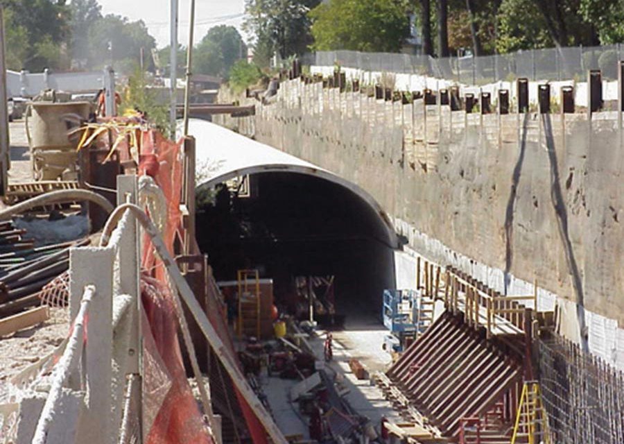
Most tunnels are actually built as trenches using cut-and-cover techniques. This St. Louis subway tunnel was built using the “bottom-up” method, using cast-in-place concrete walls and precast roof segments.
The vast majority of below-grade “tunneling” projects today are actually created using cut-and-cover construction methods. This method—in which a trench is excavated from the surface, then re-covered—is usually more economical and more practical than mined or bored tunneling. It’s especially practical at shallow depths (30 or 40 feet) but depths to 60 feet are not uncommon.
Cut-and-cover tunneling is extremely versatile. Most of the world’s subways have been built using cut-and-cover techniques. It’s the overwhelming method of choice for traffic, rail and pedestrian underpasses, utility tunnels, and a host of other applications.
Construction Methods
Depending on the situation, a variety of different construction methods can be used. Stacy Byrd, National Products Manager at CETCO, says, “There are so many different methods of constructing a tunnel and the waterproofing solution should be designed to fit that particular project and the expected jobsite conditions.”
Byrd continues, “To determine the best waterproofing solution, one must consider how the tunnel will be constructed. Will it be constructed with cast-in-place concrete, precast, shotcrete, or a combination such as a precast tunnel roof placed onto cast-in-place walls? Access is also a defining factor in product selection. Will the waterproofer have the space to install the membrane from the exterior or will it be blindside construction?”
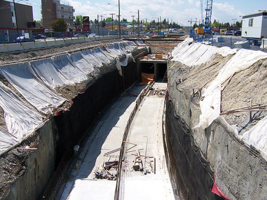
The Calgary light rail tunnels reached 60 feet below grade, and used a combination of soil nails, shotcrete, and cutback slopes that waterproofers had to work around.
Major factors determining the construction method include the excavation depth, soil type, elevation of the water table, site access, and the amount of time which the final “at grade” surface can be disturbed.
In general, the many different construction method used to build cut-and-cover tunnels can be divided into three major categories. Each of them requires an entirely different approach to waterproofing.
Bottom-Up Construction: The most common technique is the “bottom-up” construction. Here, a trench is excavated from the surface downward. Once the final depth is reached, the tunnel floor is built, then the walls and roof are put into place. Finally, the entire structure is buried and the surface restored.
If the construction site has plenty of room, the trench is usually “cut back.” Walls are typically cast in place, and the waterproofing can be applied to the outside face of the concrete with minimal problems.
Usually, though, there’s not enough room for positive side waterproofing. Especially in urban settings, where most cut-and-and cover tunnels are built, land is at a premium, so the excavation is cut vertically and reinforced with soldier piles or soil nails. In these cases, the waterproofing is done “blindside.” With this construction method, the walls (usually shotcrete or using removeable forms on the exposed face) are poured after the waterproofing is finished.
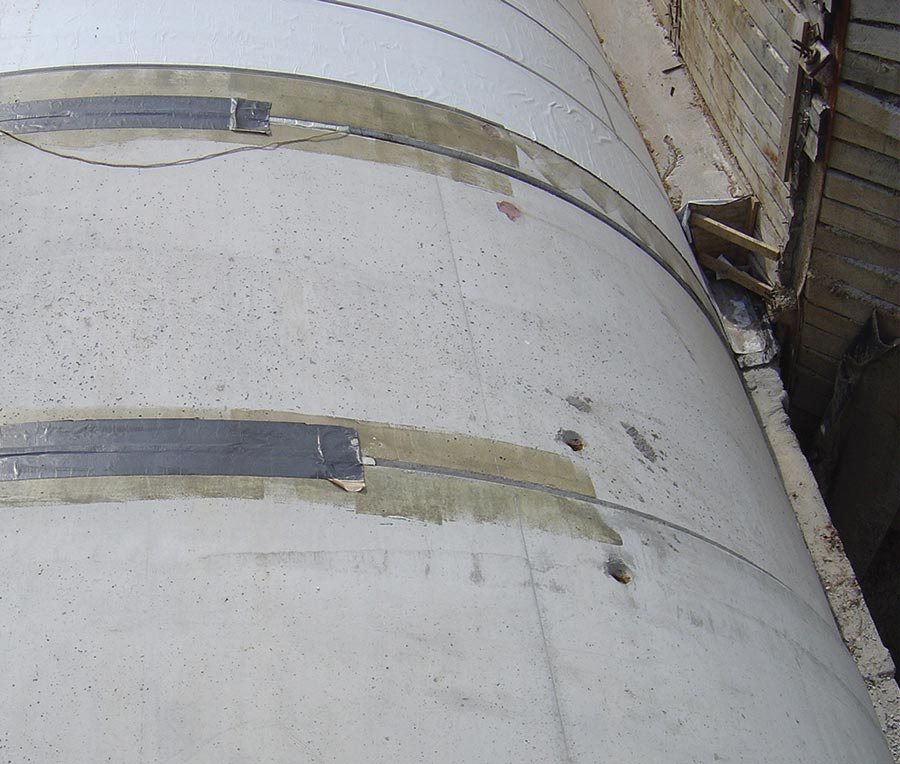
All of the joints in the precast roof segments of the St. Louis subway tunnel at left were detailed and sealed before the waterproofing and drainage layers were installed.
Roofs can be poured in place or formed with precast planks. The roof waterproofing is then tied into the wall waterproofing and drainage, and then the whole system is buried.
Bottom-up construction offers several advantages: First, it’s well understood by contractors, so finding skilled labor isn’t a problem. Additionally, waterproofing and drainage systems can be applied to the outside surface of the structure. The floor of the excavation is easily accessible for equipment and for the delivery, storage and placement of materials.
For these reasons, bottom-up construction is perhaps the most economical method of building large, shallow tunnels, but has the disadvantage of making the site unusable longer than either of the other methods detailed below.
Dave Polk, owner of Epro Services, has been involved with a number of complex tunnel projects, including the Calgary light rail extension.
“Calgary was cut-and cover,” says Polk, at Epro, ‘but it was a little different because portions of it were open-cut.” Polk adds that the deepest areas reach 60 feet below grade, and that parts of the line are a dual tunnel layout.
“We did underslab on everything,” says Polk. “It’s a 60-mil HDPE film, and that underslab system is bath-tubbed up the wall to water table height.” Once the walls were in place, the roof was poured in place in 15-foot sections using slip forms.
The roof experienced a tremendous amount of construction traffic during the backfill process, so the membrane chosen had to be extremely durable.
“We started with a spray-applied liquid membrane, and then laid down a fabric reinforcement,’ says Polk. “Then we spray another membrane over that, which creates a reinforced monolithic membrane that will stand up to site conditions. That was covered with a 15-mil polyolefin film, and then a heavy duty drainage composite, which we tied into the composite on the walls.”
CETCO was involved with waterproofing the recent extension of the below-ground St. Louis light rail, which used bottom-up cut-and-cover construction for the walls and a pre-cast roof.
Byrd explains. “Because it was going through residential sections of the community, they couldn’t overexcavate and had to pour the tunnel walls directly onto the soil retention system. We provided a bentonite-geotextile membrane that was installed to the soil retention wall prior to the concrete placement. The bentonite geotextile membrane was also used as an underslab barrier over the gravel substrate.”
The precast arched concrete segments for the roof were waterproofed using a peel-and-stick butyl rubber membrane that tied into the system used on the walls.
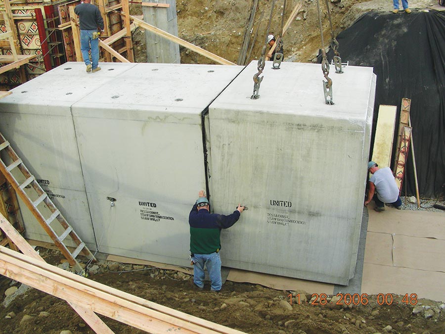
Modular Tunnels: For small tunnels, such as utility or sewer access tunnels and pedestrian underpasses, a variation on bottom-up construction can be used. Called “modular tunnels,” this construction method uses corrugated steel or pre-cast concrete segments to create the structure. These segments are usually waterproofed offsite and craned into place.
One of the primary challenges with waterproofing precast tunnels, then, is ensuring that the membrane is not damaged between when it is applied and when the tunnel segments are set into place. To ensure the waterproofing and drainage components stay in constant contact with the bottom of the precast section, designers often call for a concrete “mud slab” instead of loose gravel at the bottom of the excavation.
Waterproofers must also pay careful attention to the many joints between the pre-cast sections to ensure the tunnel remains dry.
A utility corridor built on the campus of the University of Connecticut in 2006 used this method. Each segment measured ten feet square and eight feet long, and was craned into place onto a four-inch thick mudslab, then waterproofed. First, the joints between each segment were sealed using Ultraseal BT, a product that combines bentonite clay with a hydrophilic polymer. Then, workers covered the roof and walls of the tunnel with Volclay, a similar sheet product that also contains a bentonite-polymer alloy.
Top-down Construction: The top-down construction method calls for the walls and roof of the tunnel to be put into place before the actual excavation takes place. The advantage of this method is that the surface is disturbed for a minimal amount of time—an important consideration if the tunnel is being built under a heavily used traffic artery.
In the top-down method, the first step is getting the temporary walls in place. These could be steel sheet piles or a concrete slurry wall. Once the walls are completed, the roof of the tunnel is constructed and the surface (usually a roadway) is restored.
The surface is then available for normal use while the tunnel excavation is carried out.
Top-down cut-and-cover tunnels use blind-side waterproofing techniques. The waterproofing membrane is typically applied between the temporary shoring wall and the permanent tunnel lining. The tunnel floor slab and the underslab barrier are typically the last part of construction to be completed.
The underpass tunnel leading to the San Jose Airport was built using this method. Site conditions were difficult, to say the least; the water table was only six feet below grade, which meant even the top of the tunnel would be below the water table.
Polk, at Epro Services, explains how the job went. “The first thing that needed to be done was the installation of construction wells and pumps—a site dewatering system,” says Polk. “They built the top of the tunnel first. They drove pilings in, then poured corbels and reinforced concrete beams on that. Once that was is place, we could waterproof the top.” By finishing the top first, surface roads could be opened sooner and minimize the traffic disturbance.
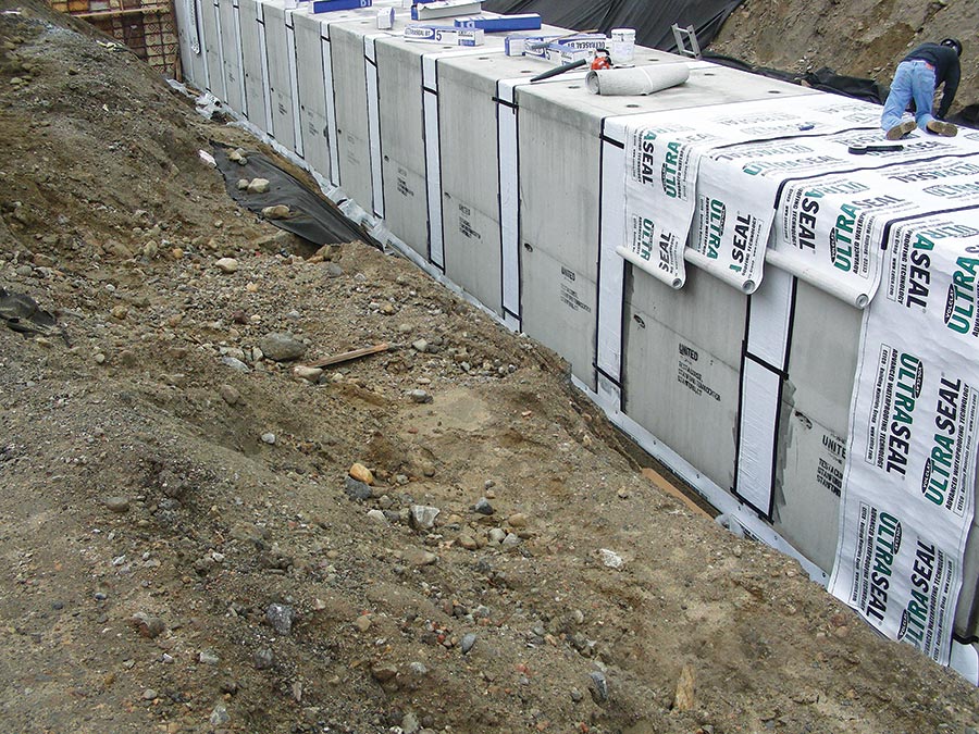
This college utility tunnel used modular precast sections. It was waterproofed using a bentonite-polymer alloy after the segments were placed in their final location.
“We used our spray membrane with a HDPE [high-density polyethylene] film over the top,” says Polk. “We knew it would be covered by paving, so we just used strip drains for drainage.”
Then they began excavating under the roof, installing post-tensioned tiebacks as the work progressed to keep the pilings stable. The tunnel bottom had to withstand 20 feet or more of hydrostatic pressure, so the waterproofing system here was absolutely critical. They used a seamless, spray-applied membrane sandwiched between two layers of HDPE.
The wall waterproofing was done blindside. Polk’s crew first applied a dimple drain sheet, then carefully sealed around the tiebacks and other penetrations. They tied this into the top and bottom waterproofing systems, then sprayed a final layer of waterproofing on the walls. Then it was enclosed in shotcrete. Completed about ten years ago, it’s still as watertight as the day it was completed.
Waterproofing Considerations
The type of waterproofing used on cut-and-cover tunnel installations usually hinges on the type of soil retention system used on the sides of the excavation. As noted above, “open cut” excavations are the easiest. Soldier piles and sheet piles are more difficult. Soil nails retention systems, which can involve detailing around literally hundreds of different points, are the most involved.
Regardless of the system used, waterproofing is essential. Not only does it reduce corrosion and maintenance and extend the life of the structure, but it can also improve safety. In colder climates, leaking tunnels can create hazardous ceiling icicles or ice patches on roadways.
Additionally, once a tunnel is placed in service, they’re extremely inconvenient to close, which imposes severe constraints on remedial waterproofing options. Particularly with rail tunnels, options for getting to—and repairing—leaking sections become extremely limited.
A few years ago, the U.S. Department of Transportation published a white paper explaining good design of cut-and cover tunnels. It places special emphasis on waterproofing. “The conception of the waterproofing system in cut-and-cover tunnels demands an exact planning of the system, a good collaboration and discussion between producer, designer of the project, main contractor and installer,” it reads. “Too often the importance of waterproofing is underestimated by the designer with the consequence that the execution of the waterproofing works are immensely difficult to achieve.”
Their study indicates that the best results can be achieved by paying special attention to “joint sealing, waterproofing of penetrations, reinforcement opti-mization, and drainage in area of the ceiling/crown.”
And cut and cover is still the primary method of constructing underground train stations. But for urban subway tunnels, cut and cover has largely been supplanted by the use of tunnel-boring machines (TBMs), which tunnel horizontally beneath the ground without disturbing the surface.
Rail Transport Infrastructure Costs
Collection of 138 tram, underground, heavy rail, and electrification projects from 14 different countries.
Some transit experts believe that this transition was a misstep. Cut and cover is a much more disruptive construction method (since it tears up the street while construction is taking place), but it’s often much cheaper than using a TBM. The Canada Line was anticipated to have 100,000 boardings per day in 2013 and 142,000 boardings per day by 2021, but it has consistently exceeded early targets. Ridership has grown steadily since opening day, with average ridership of 83,000 per day in September 2009, 105,000 per day in March 2010, and over 136,000 passengers per weekday in June 2011. During the 17 days of the 2010 Winter Olympics, the line carried an average of 228,190 passengers per day.
Governance of the project was through Canada Line Rapid Transit Inc. (CLCO), formerly RAV Project Management Ltd. (RAVCO), a reflection of the original “Richmond–Airport–Vancouver” name).
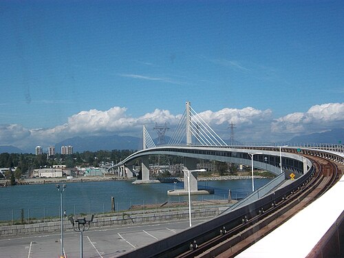
This section has some portions where the two sets of tracks are stacked vertically. The line emerges from the ground just south of 64th Avenue, climbing to an elevated guideway. Portions of the airport branch are at grade in order to accommodate a future elevated taxiway for aircraft over the line. Both branches narrow to a single track as they approach their respective terminus stations. Just before Bridgeport station is the Operations and Maintenance Centre (OMC) facility, which houses Canada Line trains that are not in use. Station construction was designed as a two-stage process. Sixteen original stations opened at the same time as the line did. Three additional stations are planned, and may be built in the future. The stations are listed below.
Each Canada Line station is slightly different in appearance, designed to blend in with the surrounding neighbourhood. The five busiest stations have platforms 50 metres (160 ft) long, while the rest of the stations have 40-metre (130 ft) platforms that can be easily extended to 50 metres. The double-tracking is necessary to accommodate the three-minute headways between trains on the Waterfront–Bridgeport portion of the line. All direct transfers to the Expo and Millennium Lines must be made at Waterfront station; there is no direct connection from Vancouver City Centre station to Granville station. However, it is possible to transfer between those two stations via a short walk through Pacific Centre or Vancouver Centre Mall.
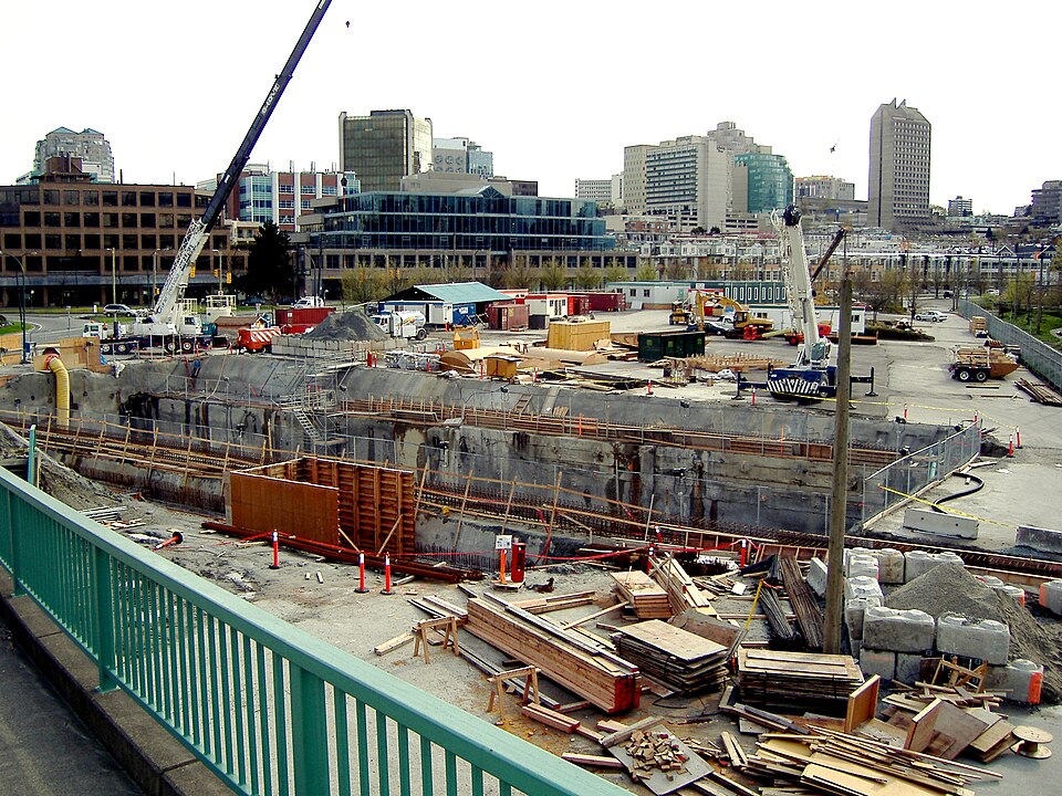
Construction taking place on the south shore of False Creek
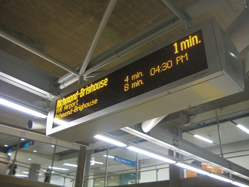
Real-time information is provided on every station platform. Stations were configured to allow for the future installation of fare gates, and received fare gates in 2013 as part of full implementation throughout all SkyTrain stations. Every station has an up escalator and an elevator, but only the three terminal stations have down escalators.
Additional stations
- 33rd Avenue (Cambie Street at West 33rd Avenue, next to Queen Elizabeth Park)[17]
- 57th Avenue (Cambie Street at West 57th Avenue)[17][18]The future of a 57th Avenue (Cambie Street and West 57th Avenue) in Vancouver is not fully known at this time. The original plan was that one day a station could be built, but new documents and talk between TransLink and the City of Vancouver raise the possibility of it never happening. The station was part of the broad policy statement adopted in 2014 by city council for the redevelopment of the Pearson Dogwood lands. But in June 2017 Susan Haid, city assistant director of planning for Vancouver South, submitted a report to Vancouver council stating that “though it is desirable to achieve a future station at 57th Avenue there are a number of key challenges,” Haid wrote in her report. “Currently, the station is not considered in regional transportation plans and is not considered a regional priority such as the Broadway Corridor line.” Haid also added to her report that, “Should the station not be attainable in the long-term future, the financial contribution towards a future station would be re-allocated to address the amenity priorities identified for Pearson Dogwood and those in and around the Cambie Corridor consistent with the respective public benefit strategies.”[19]
- YVR Terminal 3 (near YVR Terminal 3)The master plan for the Vancouver International Airport for 2027 indicates that this station would be built alongside the airport’s proposed Northeast Terminal expansion.[17][20]
Transit connections
.png)
Many transit services connect with the Canada Line and form an important part of the service. With the opening of the line, most bus routes in Richmond, and connecting services from White Rock, Tsawwassen, and Ladner, doubled their service frequency. As indicated in material presented by the City of Vancouver at public meetings in early 2006, this station was designed with such a future extension in mind. A “knock-out” panel was installed in the concourse that would facilitate construction of a connection between the station and a Broadway-corridor SkyTrain extension.
The Canada Line uses the same fare system as the rest of the transit system managed by TransLink, with two exceptions:
- The YVR AddFare, started in January 2010, is a surcharge that applies to some passengers leaving the airport and travelling eastbound to Bridgeport station and beyond. Passengers headed away from the airport must pay a $5 AddFare on top of the regular fare to leave the Sea Island stations unless they are travelling on a monthly pass; or a DayPass or a single-use Compass Ticket that was not purchased on Sea Island.
- Travel between the Sea Island stations is free to everyone. There is no additional fare for passengers travelling toward the airport. Such trips require a special Sea Island ticket that is free to obtain at any ticket machine at the Sea Island stations. These tickets are not valid for tapping out at other stations; an exit ticket is required for Sea Island ticketholders exiting at any station outside of Sea Island.
The Canada Line operates on a “Fare Paid Zone” system. Passengers are required by law to possess a valid fare when they are in Fare Paid Zones. Fare Paid Zones are clearly marked, and fares can be bought from Compass Vending Machines at all stations. Passengers who fail to pay the fare or do not have a valid fare may be fined $173 and/or removed from the station or train.
Canada Line attendants are the customer service staff for the Canada Line. They are easily identifiable by their green uniforms. They provide customer service, troubleshoot certain problems with the trains, observe and report safety issues, and check fares. The selection of Rotem was largely a consequence of the request for proposals process for the public–private partnership, whose terms did not allow Bombardier to consider efficiencies in combining operations or rolling-stock orders for the new line with those for the existing system. This placed all bidders on a level playing field, albeit at the cost of not necessarily picking the most efficient choice for long-term operation. The RFP also required that the system have a capacity of 15,000 passengers per hour in each direction (leaving the choice of technology and platform length to the proponent) and a maximum travel time between the airport and downtown Vancouver of 24 minutes.
The fleet consists of 32 fully automated two-car articulated trains, for a total of 64 cars. The trains have a top speed of 80 kilometres per hour (50 mph) in normal operation and 90 kilometres per hour (56 mph) in catch-up mode. Each married pair of gangway-connected cars is 41 metres (135 ft) long and 3 metres (9.8 ft) wide, and longer and wider than the Bombardier ART fleet used on the Expo and Millennium lines. Each train has LED electronic displays on the exterior to indicate the terminus station and on the interior to display the next station and the terminus station, a useful feature considering the line has two branches.
In 2018, twelve additional trainsets were ordered by Translink from Hyundai Rotem at a cost of $88 million to increase capacity on the line. The sole-source contract allowed for commonality between the two train models, and reduced the number of specialized tools and parts required. These were delivered in 2019 and 2020. From September 1991 through August 1993, the TRANSPORT 2021 Steering Committee carried out an extensive program of research and public consultation to create “A Long Range Transportation Plan for Greater Vancouver”. Under Project Director M. L. (Martin Crilly), a comprehensive transportation investment and financing strategy was envisioned for the region. Until today all existing and proposed road and transit investments have been put forth in this plan. The plan calls for the provision of an intermediate-capacity transit system from Richmond to Vancouver’s central business district. In fall of 1994, N. D. Lea and consultants carried out studies examining technologies, operating feasibility, ridership, capital and operating costs, traffic impacts, and development potential in three corridors, including the Richmond–Vancouver corridor. These studies were prepared as input into BC Transit’s 10-Year Development Plan. They did not include a spur line to the Vancouver International Airport.
Underground rights-of-way were reserved at the Concord Pacific development close to the Cambie bridge.
From mid-1997 to mid-1998 a number of BRT routes for Vancouver-airport/Richmond were evaluated, and the preferred route and station locations were selected.